I have seen some higher quality low voltage fittings in the past. Some even had a relay to preheat the cathodes. There was a Transtar one for the fitting above a bus door which constantly pre-heats the cathodes as the tube would be on and off all the time.All present day EM inverters supply HF AC to the tube, which is the best for tube life
The problem is with the power - common EM inverters supply about 4W or so into a 8W tube without any cathode heating, so it runs cold but at a high enough power to sputter the cathodes fast
In fittings where the same tube is switched to line gear when the line voltage is restored, the gear will finish off a tube that got initial damage from the EM gear
Why are fluorescent tubes which have ran on emergency light gear more likely to cause mercury starvation?
-
Oliver

- Posts: 1107
- Joined: Tue Nov 06, 2018 5:48 pm
- Location: County Durham
Re: Why are fluorescent tubes which have ran on emergency light gear more likely to cause mercury starvation?
-
Ash

- Posts: 399
- Joined: Sat Dec 02, 2017 9:42 pm
Re: Why are fluorescent tubes which have ran on emergency light gear more likely to cause mercury starvation?
There were EM units which preheat the tube from secondary windings on the step up transformer, and i know of one (Gaash from early 90s) that preheated one cathode (allthough still supplying AC)
All EM gear we had here was either EM-only (with or without a 2nd switchstart tube), or EM that switches the tube out of a switchstart circuit with a relay
I only seen here in the gallery 8W EM gear that somehow combines the line voltage and EM operations (whether by preheating the tube or running it from the inverter on line voltage)
The keeping of tube preheated beforehand in an EM fitting have no effect on the tube life. It will only affect the first second of starting, but then it is only the EM inverter that powers the tube. Power outages dont start frequently enough for those second of starting at a time to matter. In contrast with the bus where the on/off operation is the main source of stress on the lamps
-
Oliver
- Posts: 1107
- Joined: Tue Nov 06, 2018 5:48 pm
- Location: County Durham
Re: Why are fluorescent tubes which have ran on emergency light gear more likely to cause mercury starvation?
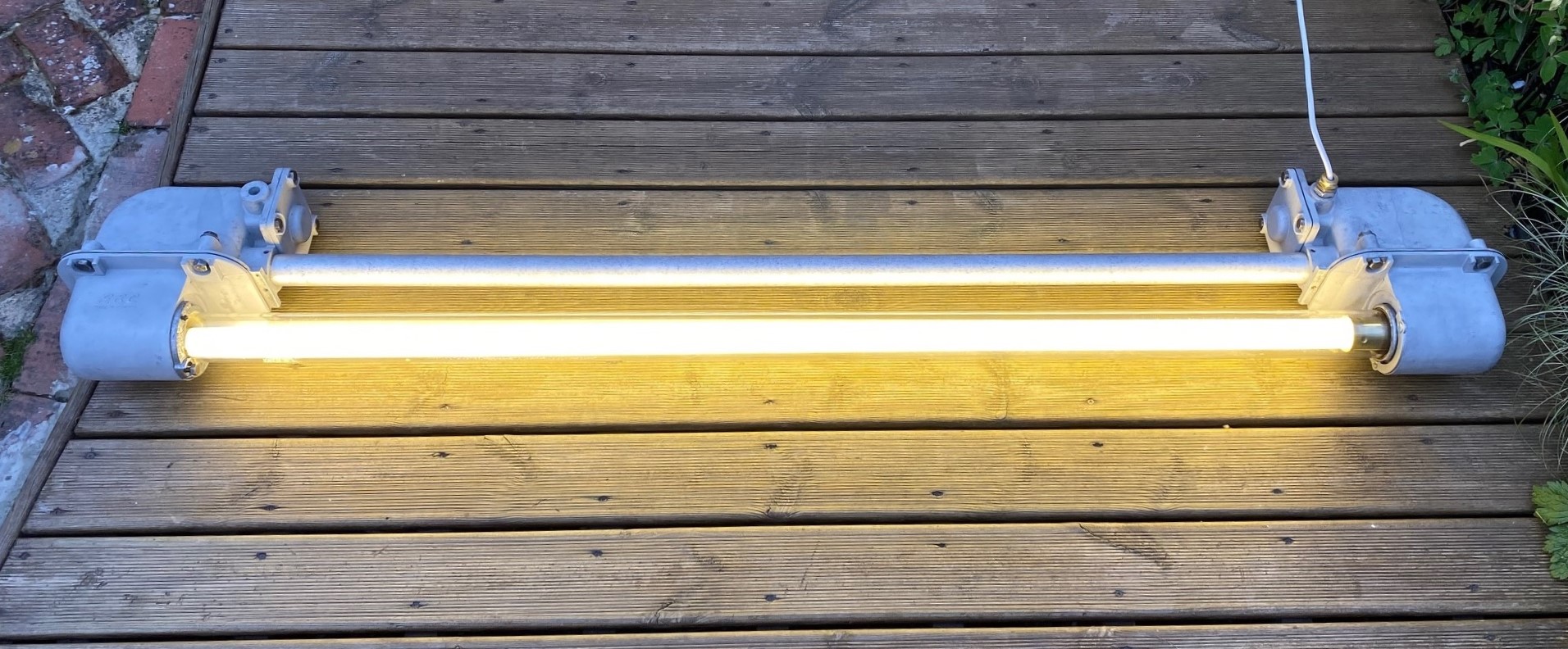
With most of my fittings, if you put one end of the tube into the lamp holder, the cathode will preheat. If a tube with intact cathodes is unable to strike, it will just stay pre-heating (similar to a stuck starter condition). I have a few fittings which have a magnetic ballast side with relay for the mains operations. The ones with 2 tubes are called sustained I think. Often those ones would have either a switch start circuit or a HF Matchbox Red for the mains side. Here's a non-maintained Newlec bulkhead pre-heating the cathodes.There were EM units which preheat the tube from secondary windings on the step up transformer, and i know of one (Gaash from early 90s) that preheated one cathode (allthough still supplying AC)
All EM gear we had here was either EM-only (with or without a 2nd switchstart tube), or EM that switches the tube out of a switchstart circuit with a relay
I only seen here in the gallery 8W EM gear that somehow combines the line voltage and EM operations (whether by preheating the tube or running it from the inverter on line voltage)
The keeping of tube preheated beforehand in an EM fitting have no effect on the tube life. It will only affect the first second of starting, but then it is only the EM inverter that powers the tube. Power outages dont start frequently enough for those second of starting at a time to matter. In contrast with the bus where the on/off operation is the main source of stress on the lamps
You do not have the required permissions to view the files attached to this post.
-
Beta 5
- Posts: 337
- Joined: Sun Jan 07, 2024 11:52 am
Re: Why are fluorescent tubes which have ran on emergency light gear more likely to cause mercury starvation?
Are the maintained ones that permanently heat the cathodes like that just using the battery stepdown transformer output as a cathode heating transformer like those used in QS, with the other "transformer" on the EM PCB just being a ballast for the arc in the tube?
Fluorescent Forever
-
GreatNorburyStDepot
- Posts: 11
- Joined: Tue Jul 23, 2024 7:16 pm
- Location: Cheshire
Re: Why are fluorescent tubes which have ran on emergency light gear more likely to cause mercury starvation?
Of course when you think about the ‘old’ switchstart fluorescent lights, these also just rely on one wire to each electrode (once the discharge has been established and the starter switch has dropped out of circuit).
”I can’t think why you want to go to London. You won’t find any better lamp posts there.”
L.S. Lowry. (1887 - 1976)
L.S. Lowry. (1887 - 1976)
-
Ash
- Posts: 399
- Joined: Sat Dec 02, 2017 9:42 pm
Re: Why are fluorescent tubes which have ran on emergency light gear more likely to cause mercury starvation?
Have a look at the cores you have there and trace the wiring / PCB traces
50 Hz cores will be made of laminations. HF (EM inverter) cores will be made of Ferrite
Transformers will have minimal to no gap in the design, so will look like any plain transformer. Often the E and I laminations in the core will be inserted from alternating directions for each layer to maximize the overlap between them (which reduces the idle inductive current), which also makes it rugged mechanically
Inductor (made to be an inductor for ballasting) will have an air gap in the core. The gap is normally inside so not directly visible, but in ones that are made in the "transformer" format, the hint visible from outside is that the E's are all on one side, I's all in the other, and there gotta be some weld or additional frame bits etc. to hold the I block so it won't detach. (Switchstart ballasts also have the gap, there the I block is held in place by the base plate which encloses it and is crimped to the E block)
I guess the ones with the preheating just supply the power to the tube through a ballast and preheat the cathodes, which would start it like any QS. This lets make use of the existing transformer (allthough requiring a bit bigger one ?) while eliminating the starter
Return to “Fluorescent Lighting”
Who is online
Users browsing this forum: No registered users