Fluorescent tester
While i always wished to have a fluo test wall similar to the one in Kev's barn, the reality is, that such a wall takes up large amounts of space, space that may otherwise be available. I therefore decided to build a special test jig, by principal similar to the one I made for R7s lamps. However there are two main differences that need to be incorporated. 
1) Size: The R7s test jig is approximately 50cm (mainly to incorporate infrared lamps). The fluorescent test jig should be able to test 8ft or 240cm fluorescent tubes-- ideally at least--. The design of two parallel 10mm Stainless rods will become to flimsy and unstable. 
2) the R7s test jig is design for a single lampholder: R7s (obviously) because it is with very few exceptions the standard for double ended lamps... (I am aware of the wast amount of special bases for studio and optical lamps as well as some unique in stadium lighting, however these lamps are so unique i only have very few examples and most of them can be divided into cable or srew terminal that can be contacted by cables... With fluorescent however you have G13 (T8-T12), G5 (T5), B22d (T12), Fa6, Fa8, R18d and that is without compact fluorescents...

So we need to adapt : We need to make it Stiffer and compatible with different lampholders. On the same time it should use readily available and therefore cheap parts as a I prefer spending my money on other things as well. 

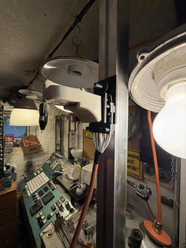
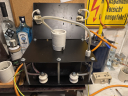
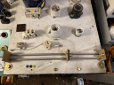
So instead of the two stainless rods i decided to use an aluminium Solar mounting rail. It is cheap and readily available at £1,50p per foot. However it allows either an M8 or M10 bolt to be slit in and secured. With the bold a sled is mounted, which can be seen in the picture. Each sled is made from two peaces of paxolin. The Paxolin was readily available because it came from crapped streetlights. It is a two stacked designs. The lower stack holds a  5 pin Wieland lighting connector. I decided to use these as they were available also from scrapped lights but also because they are very well designed and rugged. I used 5 pins one so i can run both (ballasted) live, neutral and both starter to each sled. That may be necessery for example when U tubes or PL-L lamps are tested. 
On the second platoon the lampholder itself is mounted. 

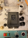
On the side is a small metal box, containing a starter socket, and a switch. The switch can be used for manual preheat and the starter socket, well for starters -- who would have thought.... Eventually i plan to add an electronic starter, most likely a thorn Vivatronic either an original (if i get my hand on one) or a self made copy of the same. Eventually i will also ad a filament heating transformer for rapid start lamps.

Fluorescent tester

While i always wished to have a fluo test wall similar to the one in Kev's barn, the reality is, that such a wall takes up large amounts of space, space that may otherwise be available. I therefore decided to build a special test jig, by principal similar to the one I made for R7s lamps. However there are two main differences that need to be incorporated.
1) Size: The R7s test jig is approximately 50cm (mainly to incorporate infrared lamps). The fluorescent test jig should be able to test 8ft or 240cm fluorescent tubes-- ideally at least--. The design of two parallel 10mm Stainless rods will become to flimsy and unstable.
2) the R7s test jig is design for a single lampholder: R7s (obviously) because it is with very few exceptions the standard for double ended lamps... (I am aware of the wast amount of special bases for studio and optical lamps as well as some unique in stadium lighting, however these lamps are so unique i only have very few examples and most of them can be divided into cable or srew terminal that can be contacted by cables... With fluorescent however you have G13 (T8-T12), G5 (T5), B22d (T12), Fa6, Fa8, R18d and that is without compact fluorescents...

So we need to adapt : We need to make it Stiffer and compatible with different lampholders. On the same time it should use readily available and therefore cheap parts as a I prefer spending my money on other things as well.

So instead of the two stainless rods i decided to use an aluminium Solar mounting rail. It is cheap and readily available at £1,50p per foot. However it allows either an M8 or M10 bolt to be slit in and secured. With the bold a sled is mounted, which can be seen in the picture. Each sled is made from two peaces of paxolin. The Paxolin was readily available because it came from crapped streetlights. It is a two stacked designs. The lower stack holds a 5 pin Wieland lighting connector. I decided to use these as they were available also from scrapped lights but also because they are very well designed and rugged. I used 5 pins one so i can run both (ballasted) live, neutral and both starter to each sled. That may be necessery for example when U tubes or PL-L lamps are tested.
On the second platoon the lampholder itself is mounted.

On the side is a small metal box, containing a starter socket, and a switch. The switch can be used for manual preheat and the starter socket, well for starters -- who would have thought.... Eventually i plan to add an electronic starter, most likely a thorn Vivatronic either an original (if i get my hand on one) or a self made copy of the same. Eventually i will also ad a filament heating transformer for rapid start lamps.

IMG_1633.jpeg IMG_1277.JPG IMG_0614.jpeg IMG_0503.JPG
File information
Filename:IMG_1277.JPG
Album name:Alex / Control Gear & Accessories
Filesize:2681 KiB
Date added:20 Jun, 2026
Dimensions:1536 x 2048 pixels
Displayed:82 times
URL:http://80.229.24.59:9232/gallery/displayimage.php?pid=25131
Favourites:Add to Favourites

Comment 1 to 1 of 1
Page: 1

AngryHorse   [22 Jun, 2026 at 10:32 AM]
Perfect Very Happy, one unit for everything Cool

Comment 1 to 1 of 1
Page: 1

Add your comment
Anonymous comments are not allowed here. Log in to post your comment